Engineers develop compact biomass powered CHP plant based on Stirling engines
 A consortium of European research organisations has achieved an engineering breakthrough by developing a compact, highly efficient combined heat-and-power (CHP) plant based on stirling engines and fueled by biomass. Until now there were no biomass CHP technologies available in the power range below 100 kWel. The engineers succeeded in optimizing and scaling down the technology to a power range of 35 kWel and a 70 kWel.
The small scale plants are hyper-efficient with an overall system efficiency ranging between 85 and 93%. Because the CHP units are so compact, they can replace existing but far less efficient traditional hot-water boilers. Alternatively they can operate in decentralised and autonomous energy systems in off-grid places, particularly in the developing world. Given that it is fueled by renewable and carbon-neutral solid biomass, the system is one of the cleanest energy concepts available.
The technology was developed within the scope of a research, development and demonstration cooperation project jointly carried out by the Technical University of Denmark, Bios Bioenergiesysteme, Mawera Holzfeuerungsanlagen and the Austrian Bioenergy Centre. Two pilot plants have been tested extensively with promising results: the smallest of the two pilot plants, the 35 kWel unit (image, click to enlarge), was tested for more than 10,000 hours, whereas the 70 kWel system has been operated for approximately 3,000 hours.
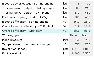
The following table shows relevant technical data and efficiencies of the CHP technology based on the 35 kWel- and the 70 kWel-Stirling engines:

 The small-scale CHP unit works on the basis of an advanced furnace, equipped with underfeed stoker technology where the biofuel is burned. In the combustion chamber the flue gas reaches temperatures of approximately 1,300 °C. Heat is then transferred to the Stirling hot heat exchanger and the temperature of the flue gas is reduced to about 800 °C at a heat exchanger outlet. Subsequently, the flue gas passes through an air preheater and an economiser mounted downstream the hot heat exchanger (schematic, click to enlarge).
Integrating, scaling and optimising the system in such a way that it can be fueled by biomass, a fuel with particular properties, presented many challenges and required several innovations:
 energy :: sustainability :: renewables :: biomass :: bioenergy :: biofuels :: efficiency :: decentralisation :: combined heat-and-power ::stirling ::
 An efficient engine
The core of the system is based on the Stirling engine. Such engines are based on a closed cycle, where the working gas is alternately compressed in a cold cylinder volume and expanded in a hot cylinder volume. The advantage of the Stirling engine in comparison to internal combustion engines is that the heat is not supplied to the cycle by combustion of the fuel inside the cylinder, but transferred from the outside through a heat exchanger in the same way as in a steam boiler. Consequently, the combustion system for a Stirling engine can be based on proven furnace technology, thus reducing combustion related problems.
The heat input from fuel combustion is transferred to the working gas through a hot heat exchanger at high temperatures. The heat that is not converted into work on the shaft is rejected to the cooling water in a cold heat exchanger.
Challenges
The Stirling engine developed at the Technical University of Denmark uses Helium as working gas and is designed as a hermetically sealed unit. The use of Helium is very efficient in the context of the electric efficiency of the engine, but the researchers found that the utilisation of this low molecular weight gas made it difficult to design a piston rod seal, which keeps the working gas inside the cylinder and prevents the lubrication oil from entering the cylinder.
Many solutions have been tested, but it is still a delicate component in the engine. An attractive option was to bypass the problem by designing the engine as a hermetically sealed unit with the generator incorporated in the pressurised crankcase, just like the electric motor in a hermetically sealed compressor for refrigeration. This way, only static seals are necessary and the only connections from the inside to the outside of the hermetically sealed crankcase are the cable connections between the generator and the grid.
The challenges presented by the utilization of biomass fuels in connection with a Stirling engine were concentrated on transferring the heat from the combustion of the fuel into the working gas. The temperature must be high in order to obtain an acceptable specific power output and efficiency, and the heat exchanger must be designed so that problems with fouling are minimised.
Because of the high temperatures in the combustion chamber and the risk of fouling, it is not possible to utilise a Stirling engine designed for natural gas, as narrow passages in the Stirling heat exchanger are blocked after less than an hour of operation with biomass fuels. The risk of fouling in biomass combustion processes is mainly due to aerosol formation and condensation of ash vapours when the flue gas gets cooled. Bios Bioenergiesysteme GmbH developed a programme calculating the heat transfer from the flue gas to the internal working gas. Based on this development comprehensive design studies were performed and the performance of the Stirling heat exchanger was improved and optimised.
The image above (click to enlarge) shows an energy flow sheet of the CHP plant based on a 35 kWel Stirling engine. The electric plant efficiency amounts to approximately 12% and the overall plant efficiency to about 85 to 92%. The thermal heat output is normally in the range of around 230 kW and the fuel capacity (based on net calorific value) amounts to 300 kW.
Innovations
Furthermore, the Bios Bioenergiesysteme developed and designed an automatic cleaning system for the Stirling heat exchanger which was subsequently optimised during plant operation. The system comprises a pressurised air tank and air nozzles at each heat exchanger panel. The nozzles are equipped with magnetic valves. The valves are opened at regular intervals (only one valve at a time, all other valves remain closed) and the air is blown into the heat exchanger sector and cleans the tubes from ash deposits. The ash is then entrained with the flue gas and subsequently collected in the fly-ash precipitators.
In order to obtain a high overall electric efficiency of the CHP plant, the temperature in the hot heat exchanger and consequently the temperature of the flue gas should be as high as possible. Therefore, it is necessary to preheat the combustion air with the flue gas leaving the hot heat exchanger by means of an air preheater. Typically the temperature of the combustion air is raised to 500 °C – 600 °C, resulting in very high temperatures in the combustion chamber. This can cause ash slagging and fouling problems in biomass combustion systems and in the hot heat exchanger.
Consequently, the design of the furnace and its adaptation to the special requirements of a CHP plant with a 35 kWel Stirling engine was an important and difficult task. The plant should operate at a high temperature level to gain a high electric efficiency from the Stirling engine but temperature peeks in the furnace should be impeded in order to reduce ash slagging and fouling. The plant is designed for temperature levels in the furnace of about 1,300 °C (the typical flue gas temperatures in conventional biomass furnaces are in the range of approx. 1,000 °C).
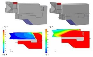
An appropriate combustion system was developed and optimised using CFD simulations which have been performed by Bios Bioenergiesysteme. The results achieved showed that it is a very important task to optimise the design of the furnace geometry, of the secondary air nozzles and the nozzles for flue gas recirculation in order to reduce temperature peaks in the furnace as well as CO emissions. In addition, the CFD simulations performed improved an equal distribution of the flue gas flow into the different sections of the hot gas heat exchanger and thus ensured an equal heat transfer to the cylinders of the Stirling engines.
Figure 2 (click to enlarge) shows the geometry of the furnace with conventional nozzle design and placement. The secondary air nozzles are placed at the inlet of the secondary combustion chamber. The results of the CFD simulations performed for this geometry show that the flue gas burn out in the secondary combustion chamber is not efficient (see Figure 4). The CO emissions at outlet according to CFD simulations are about 100 mg/Nm3 (dry flue gas, 13 vol% O2).
Figure 3 shows a furnace geometry with optimised nozzle design and placement. The secondary air nozzles are arranged horizontally in the transition zone between primary and secondary combustion chamber. With this configuration the combustion air is efficiently mixed with the flue gas and a swirl flow is established in the secondary combustion chamber. Consequently, the resulting CO emissions are low. Figure 5 shows the contours of CO in mg/Nm3 calculated for the geometry with optimised air nozzles. For the optimised geometry, CFD simulations predict CO emission of approx. 15 mg/Nm3 (dry flue gas, 13 vol% O2). The results demonstrate that an efficient turbulent flow enhances the combustion process and reduces CO emissions, which stresses the relevance of an optimisation of the combustion system supported by CFD analyses.
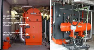
The image above (click to enlarge) shows the 35 kWel pilot plant. The furnace of the CHP plant is equipped with underfeed stoker technology. The Stirling engine is mounted in a horizontal position downstream of the secondary combustion chamber for convenient maintenance. The air pre-heater and the economiser are placed on top of the furnace in order to achieve a compact design of the plant. To remove fly ash particles from the hot gas heat exchanger, a pneumatic and fully automatic cleaning system was developed and installed.
References:
Friedrich Biedermann, Henrik Carlsen, Martin Schöch, Ingwald Obernberger, "Operating experiences with a small-scale CHP pilot plant based on a 35kWel hermetic four cylinder stirling engine for biomass fuels" [*.pdf].
 --------------
 The Bowen Group, one of Ireland's biggest construction groups has announced a strategic move into the biomass energy sector. It is planning a €25 million investment over the next five years to fund up to 100 projects that will create electricity from biomass. Its ambition is to install up to 135 megawatts of biomass-fuelled heat from local forestry sources, which is equal to 50 million litres or about €25m worth of imported oil.


1 Comments:
The information in this article is a few years old. The technology is now commercially available. The biomass boiler plants discussed in this text are sold through Mawera in Austria. The engines are produced by a newly created Danish company "Stirling Danmark Aps" who also offers turn key plants based on gasification of wood chips and the 35 kW engine. Please see Stirling.dk for more information.
Jesper Noes, Stirling Danmark Aps
Post a Comment
Links to this post:
Create a Link
<< Home